Thursday, September 29, 2022

Computer Organization and Architecture (Solved Answers from QBank - V) - Tirthankar Pal - MBA from IIT Kharagpur, GATE, GMAT, IIT Written Test, Interview were a part of MBA Entrance, B.S. in Computer Science from NIELIT

Latency

Memory latency and memory access times are used interchangeably many times, however, they are different in certain cases and depends on the type of memory under consideration.

However, I believe we can go with below definitions for being generic.

Memory latency : The time taken for accessing a memory starting from making a request to getting the data.

Memory access (Average memory access) : It refers to the *average time taken for accessing a memory starting from making a request for getting the data.

*Average time taken = mean time taken in different memory access which includes hits/misses/fails for a request to memory

What Is Bandwidth?

Bandwidth refers to the amount of data that can be transmitted and received during a specific period of time. For instance, if a network has high bandwidth, this means a higher amount of data can be transmitted and received.

Like throughput, the unit of measurement for bandwidth is bits per second (bps). Bandwidth can also be measured in gigabits per second (Gbps) and megabits per second (Mbps). High bandwidth doesn’t necessarily guarantee optimal network performance. If, for example, the network throughput is being impacted by packet loss, jitter, or latency, your network is likely to experience delays even if you have high bandwidth availability.

Sometimes, bandwidth is confused with speed, but this is a widespread misconception. Bandwidth measures capacity, not speed. This misconception is often perpetuated by internet service providers peddling the idea that high-speed services are facilitated by maximum bandwidth availability. While this may make for a convincing advertisement, high bandwidth availability doesn’t necessarily translate into high speeds. In fact, if your bandwidth is increased, the only difference is a higher amount of data can be transmitted at any given time. Although the ability to send more data might seem to improve network speeds, increasing bandwidth doesn’t increase the speed of packet transmission.

In reality, bandwidth is one of the many factors that contribute to network speed. Speed measures response time in a network, and response time will also be impacted by factors like latency and packet loss rates.

Memory Cycle time 

It is the total time that is required to store next memory access operation from the previous memory access operation. Memory cycle time = access time plus transient time (any additional time required before a second access can commence). — Time may be required for the memory to “recover” before next access — Cycle time is access + recovery

Differentiate between Programmed driven I/O and Interrupt driven I/O

Data transfer between the CPU and I/O devices can be done in variety of modes. These are three possible modes: 
 

  1. Programmed I/O
  2. Interrupt initiated I/O
  3. Direct Memory Access (DMA)

In this article we shall discuss the first two modes only. 

1. Programmed I/O : 
In this mode the data transfer is initiated by the instructions written in a computer program. An input instruction is required to store the data from the device to the CPU and a store instruction is required to transfer the data from the CPU to the device. Data transfer through this mode requires constant monitoring of the peripheral device by the CPU and also monitor the possibility of new transfer once the transfer has been initiated. Thus CPU stays in a loop until the I/O device indicates that it is ready for data transfer. Thus programmed I/O is a time consuming process that keeps the processor busy needlessly and leads to wastage of the CPU cycles. 
This can be overcome by the use of an interrupt facility. This forms the basis for the Interrupt Initiated I/O. 

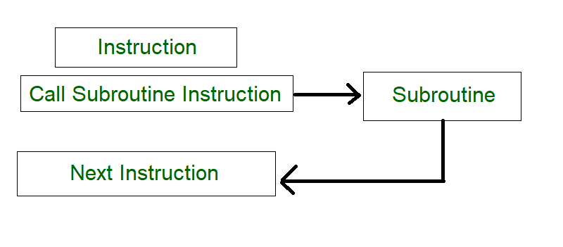
2. Interrupt Initiated I/O : 
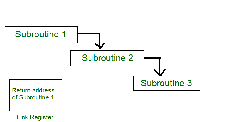
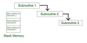
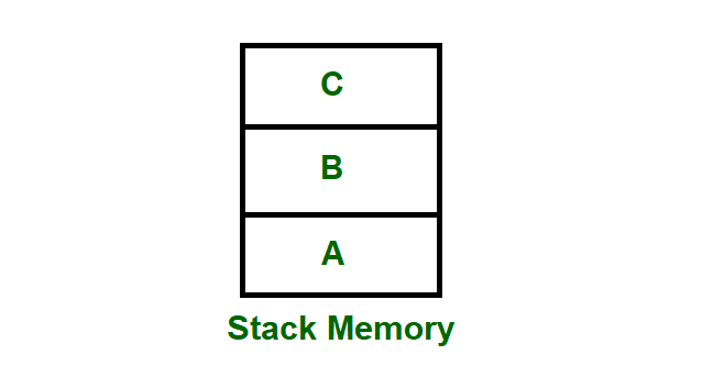
This mode uses an interrupt facility and special commands to inform the interface to issue the interrupt command when data becomes available and interface is ready for the data transfer. In the meantime CPU keeps on executing other tasks and need not check for the flag. When the flag is set, the interface is informed and an interrupt is initiated. This interrupt causes the CPU to deviate from what it is doing to respond to the I/O transfer. The CPU responds to the signal by storing the return address from the program counter (PC) into the memory stack and then branches to service that processes the I/O request. After the transfer is complete, CPU returns to the previous task it was executing. The branch address of the service can be chosen in two ways known as vectored and non-vectored interrupt. In vectored interrupt, the source that interrupts, supplies the branch information to the CPU while in case of non-vectored interrupt the branch address is assigned to a fixed location in memory. 

Tirthankar Pal

MBA from IIT Kharagpur with GATE, GMAT, IIT Kharagpur Written Test, and Interview

2 year PGDM (E-Business) from Welingkar, Mumbai

4 years of Bachelor of Science (Hons) in Computer Science from the National Institute of Electronics and Information Technology

Google and Hubspot Certification

Brain Bench Certification in C++, VC++, Data Structure and Project Management

10 years of Experience in Software Development out of that 6 years 8 months in Wipro

Selected in Six World Class UK Universities:-

King's College London, Durham University, University of Exeter, University of Sheffield, University of Newcastle, University of Leeds

Computer Organization and Architecture (Solved Answers from QBank - IV) - Tirthankar Pal - MBA from IIT Kharagpur, GATE, GMAT, IIT Written Test, Interview were a part of MBA Entrance, B.S. in Computer Science from NIELIT

 Floating Point Arithmetic Unit

The objectives of this module are to discuss the need for floating point numbers, the standard representation used for floating point numbers and discuss how the various floating point arithmetic operations of addition, subtraction, multiplication and division are carried out.


Floating-point numbers and operations


Representation


When you have to represent very small or very large numbers, a fixed point representation will not do. The accuracy will be lost. Therefore, you will have to look at floating-point representations, where the binary point is assumed to be floating. When you consider a decimal number 12.34 * 107, this can also be treated as 0.1234 * 109, where 0.1234 is the fixed-point mantissa. The other part represents the exponent value, and indicates that the actual position of the binary point is 9 positions to the right (left) of the indicated binary point in the fraction. Since the binary point can be moved to any position and the exponent value adjusted appropriately, it is called a floating-point representation. By convention, you generally go in for a normalized representation, wherein the floating-point is placed to the right of the first nonzero (significant) digit. The base need not be specified explicitly and the sign, the significant digits and the signed exponent constitute the representation.


The IEEE (Institute of Electrical and Electronics Engineers) has produced a standard for floating point arithmetic. This standard specifies how single precision (32 bit) and double precision (64 bit) floating point numbers are to be represented, as well as how arithmetic should be carried out on them. The IEEE single precision floating point standard representation requires a 32 bit word, which may be represented as numbered from 0 to 31, left to right. The first bit is the sign bit, S, the next eight bits are the exponent bits, ‘E’, and the final 23 bits are the fraction ‘F’. Instead of the signed exponent E, the value stored is an unsigned integer E’ = E + 127, called the excess-127 format. Therefore, E’ is in the range 0 £ E’ £ 255.


S E’E’E’E’E’E’E’E’ FFFFFFFFFFFFFFFFFFFFFFF


0 1                                     8  9                                                                    31


The value V represented by the word may be determined as follows:


  • If E’ = 255 and F is nonzero, then V = NaN (“Not a number”)
  • If E’ = 255 and F is zero and S is 1, then V = -Infinity
  • If E’ = 255 and F is zero and S is 0, then V = Infinity
  • If 0 < E< 255 then V =(-1)**S * 2 ** (E-127) * (1.F) where “1.F” is intended to represent the binary number created by prefixing F with an implicit leading 1 and a binary point.
  • If E’ = 0 and F is nonzero, then V = (-1)**S * 2 ** (-126) * (0.F). These are “unnormalized” values.
  • If E’= 0 and F is zero and S is 1, then V = -0
  • If E’ = 0 and F is zero and S is 0, then V = 0

For example,


0 00000000 00000000000000000000000 = 0


1 00000000 00000000000000000000000 = -0


0 11111111 00000000000000000000000 = Infinity


1 11111111 00000000000000000000000 = -Infinity


0 11111111 00000100000000000000000 = NaN


1 11111111 00100010001001010101010 = NaN


0 10000000 00000000000000000000000 = +1 * 2**(128-127) * 1.0 = 2


0 10000001 10100000000000000000000 = +1 * 2**(129-127) * 1.101 = 6.5


1 10000001 10100000000000000000000 = -1 * 2**(129-127) * 1.101 = -6.5


0  00000001 00000000000000000000000 = +1 * 2**(1-127) * 1.0 = 2**(-126)


0  00000000 10000000000000000000000 = +1 * 2**(-126) * 0.1 = 2**(-127)


0  00000000 00000000000000000000001 = +1 * 2**(-126) *


0.00000000000000000000001 = 2**(-149) (Smallest positive value)


(unnormalized values)


Double Precision Numbers:


The IEEE double precision floating point standard representation requires a 64-bit word, which may be represented as numbered from 0 to 63, left to right. The first bit is the sign bit, S, the next eleven bits are the excess-1023 exponent bits, E’, and the final 52 bits are the fraction ‘F’:


S  E’E’E’E’E’E’E’E’E’E’E’


FFFFFFFFFFFFFFFFFFFFFFFFFFFFFFFFFFFFFFFFFFFFFFFFFFFF


0 1                                                     11 12


63


The value V represented by the word may be determined as follows:

  • If E’ = 2047 and F is nonzero, then V = NaN (“Not a number”)
  • If E’= 2047 and F is zero and S is 1, then V = -Infinity
  • If E’= 2047 and F is zero and S is 0, then V = Infinity
  • If 0 < E’< 2047 then V = (-1)**S * 2 ** (E-1023) * (1.F) where “1.F” is intended to represent the binary number created by prefixing F with an implicit leading 1 and a binary point.
  • If E’= 0 and F is nonzero, then V = (-1)**S * 2 ** (-1022) * (0.F) These are “unnormalized” values.
  • If E’= 0 and F is zero and S is 1, then V = – 0
  • If E’= 0 and F is zero and S is 0, then V = 0


Arithmetic unit


Arithmetic operations on floating point numbers consist of addition, subtraction, multiplication and division. The operations are done with algorithms similar to those used on sign magnitude integers (because of the similarity of representation) — example, only add numbers of the same sign. If the numbers are of opposite sign, must do subtraction.


ADDITION


Example on decimal value given in scientific notation:


3.25 x 10 ** 3

+ 2.63 x 10 ** -1

—————–

    first step: align decimal points

second step: add


3.25       x 10 ** 3

+  0.000263 x 10 ** 3

——————–

3.250263 x 10 ** 3

(presumes use of infinite precision, without regard for accuracy)


third step:  normalize the result (already normalized!)


Example on floating pt. value given in binary:


.25 =    0 01111101 00000000000000000000000

 100 =    0 10000101 10010000000000000000000

To add these fl. pt. representations,


step 1:  align radix points


shifting the mantissa left by 1 bit decreases the exponent by 1


shifting the mantissa right by 1 bit increases the exponent by 1


we want to shift the mantissa right, because the bits that fall off the end should come from the least significant end of the mantissa


-> choose to shift the .25, since we want to increase it’s exponent.

-> shift by  10000101

-01111101

———

00001000    (8) places.


0 01111101 00000000000000000000000 (original value)

0 01111110 10000000000000000000000 (shifted 1 place)

(note that hidden bit is shifted into msb of mantissa)

0 01111111 01000000000000000000000 (shifted 2 places)

0 10000000 00100000000000000000000 (shifted 3 places)

0 10000001 00010000000000000000000 (shifted 4 places)

0 10000010 00001000000000000000000 (shifted 5 places)


0 10000011 00000100000000000000000 (shifted 6 places)

0 10000100 00000010000000000000000 (shifted 7 places)

0 10000101 00000001000000000000000 (shifted 8 places)


step 2: add (don’t forget the hidden bit for the 100)


0 10000101 1.10010000000000000000000  (100)

+    0 10000101 0.00000001000000000000000  (.25)

—————————————

0 10000101 1.10010001000000000000000


step 3:  normalize the result (get the “hidden bit” to be a 1)

It already is for this example.

result is0 10000101 10010001000000000000000


SUBTRACTION


Same as addition as far as alignment of radix points

Then the algorithm for subtraction of sign mag. numbers takes over.


before subtracting,

compare magnitudes (don’t forget the hidden bit!)

change sign bit if order of operands is changed.


don’t forget to normalize number afterward.


MULTIPLICATION


Example on decimal values given in scientific notation:


3.0 x 10 ** 1

+  0.5 x 10 ** 2

—————–


Algorithm:  multiply mantissas

add exponents


3.0 x 10 ** 1

+  0.5 x 10 ** 2

—————–

1.50 x 10 ** 3


Example in binary:     Consider a mantissa that is only 4 bits.


0 10000100 0100

x 1 00111100 1100


Add exponents:


always add true exponents (otherwise the bias gets added in twice)

DIVISION

It is similar to multiplication.

do unsigned division on the mantissas (don’t forget the hidden bit)

subtract TRUE exponents


The organization of a floating point adder unit and the algorithm is given below.


The floating point multiplication algorithm is given below. A similar algorithm based on the steps discussed before can be used for division.


Rounding


The floating point arithmetic operations discussed above may produce a result with more digits than can be represented in 1.M. In such cases, the result must be rounded to fit into the available number of M positions. The extra bits that are used in intermediate calculations to improve the precision of the result are called guard bits. It is only a tradeoff of hardware cost (keeping extra bits) and speed versus accumulated rounding error, because finally these extra bits have to be rounded off to conform to the IEEE standard.


Rounding Methods:

  • Truncate


–   Remove all digits beyond those supported

–   1.00100 -> 1.00

  • Round up to the next value


–   1.00100 -> 1.01

  • Round down to the previous value


–   1.00100 -> 1.00

–   Differs from Truncate for negative numbers

  • Round-to-nearest-even


–   Rounds to the even value (the one with an LSB of 0)

–   1.00100 -> 1.00

–   1.01100 -> 1.10

–   Produces zero average bias

–   Default mode

A product may have twice as many digits as the multiplier and multiplicand

–   1.11 x 1.01 = 10.0011


For round-to-nearest-even, we need to know the value to the right of the LSB (round bit) and whether any other digits to the right of the round digit are 1’s (the sticky bit is the OR of these digits). The IEEE standard requires the use of 3 extra bits of less significance than the 24 bits (of mantissa) implied in the single precision representation – guard bit, round bit and sticky bit. When a mantissa is to be shifted in order to align radix points, the bits that fall off the least significant end of the mantissa go into these extra bits (guard, round, and sticky bits). These bits can also be set by the normalization step in multiplication, and by extra bits of quotient (remainder) in division. The guard and round bits are just 2 extra bits of precision that are used in calculations. The sticky bit is an indication of what is/could be in lesser significant bits that are not kept. If a value of 1 ever is shifted into the sticky bit position, that sticky bit remains a 1 (“sticks” at 1), despite further shifts.


To summarize, in his module we have discussed the need for floating point numbers, the IEEE standard for representing floating point numbers, Floating point addition / subtraction, multiplication, division and the various rounding methods.


Tirthankar Pal

MBA from IIT Kharagpur with GATE, GMAT, IIT Kharagpur Written Test, and Interview

2 year PGDM (E-Business) from Welingkar, Mumbai

4 years of Bachelor of Science (Hons) in Computer Science from the National Institute of Electronics and Information Technology

Google and Hubspot Certification

Brain Bench Certification in C++, VC++, Data Structure and Project Management

10 years of Experience in Software Development out of that 6 years 8 months in Wipro

Selected in Six World Class UK Universities:-

King's College London, Durham University, University of Exeter, University of Sheffield, University of Newcastle, University of Leeds


Computer Organization and Architecture (Solved Answers from QBank - III) - Tirthankar Pal - MBA from IIT Kharagpur, GATE, GMAT, IIT Written Test, Interview were a part of MBA Entrance, B.S. in Computer Science from NIELIT

Processor Stack, Stack Frame, and Frame Pointer

Stack Frame :

Stack is one of the segments of application memory that is used to store the local variables, function calls of the function. Whenever there is a function call in our program the memory to the local variables and other function calls or subroutines get stored in the stack frame. Each function gets its own stack frame in the stack segment of the application’s memory. 

Features :

  • The memory allocated for a function call in the stack lives only the time when the function is executing once the function gets completed we can’t access the variables of that function.
  • Once the calling function completes its execution its stack frame is removed and the thread of execution of called function resumes from that position where it was left.
  • Stack is used for storing function calls so in the case when we are using a lot of recursive calls in our program the stack memory gets exhausted by the function calls or subroutines which may result in stack overflow because the stack memory is limited.
  • Each stack frame maintains the Stack Pointer (SP), and the frame pointer (FP).  Stack pointer and frame pointer always point to the top of the stack. It also maintains a program counter (PC) which points to the next instruction to be executed.
  • Whenever a function call is made a stack frame is created in the stack segment the arguments that were given by the calling function get some memory in the stack frame of called function, and they get pushed into the stack frame of the called function. When their execution is finished they get popped from the stack frame. And the thread of execution gets continues in the called function.

Structure of stack frame :
Stack pointer always points to the top and frame pointer stores address of whole stack frame of the subroutine. Each stack frame of a subroutine or a function contains as follows. 

Stack Frame
Other function calls
Other saved registers 
Local variables
Saved [Frame Pointer]
Of called function
Saved [Link Register]
Of called function
Passed arguments 
Frame pointer (F.P)

1. Subroutine:
A set of instructions that are used repeatedly in a program can be referred to as Subroutine. Only one copy of this Instruction is stored in the memory. When a Subroutine is required it can be called many times during the Execution of a particular program. A call Subroutine Instruction calls the Subroutine. Care Should be taken while returning a Subroutine as Subroutine can be called from a different place from the memory. 

The content of the PC must be Saved by the call Subroutine Instruction to make a correct return to the calling program. 

Figure – Process of a subroutine in a program 

Figure – Subroutine calling another subroutine 

From the above figure, assume that when Subroutine 1 calls Subroutine 2 the return address of Subroutine 2 should be saved somewhere. So if the link register stores the return address of Subroutine 1 this will be (destroyed/overwritten) by the return address of Subroutine 2. As the last Subroutine called is the first one to be returned ( Last in first out format). So stack data structure is the most efficient way to store the return addresses of the Subroutines. 

Figure – Return address of subroutine is stored in stack memory

3. Stack memory:

Stack is a basic data structure that can be implemented anywhere in the memory. It can be used to store variables that may be required afterward in the program Execution. In a stack, the first data put will be the last to get out of a stack. So the last data added will be the first one to come out of the stack (last in first out). 

Figure – Stack memory having data A, B & C

So from the diagram above first A is added then B & C. While removing first C is Removed then B & A.

\Register $30 is reserved, by software convention, for use as a frame pointer. In the extended assembler it has the mnemonic name $fp. When a subroutine starts running, the frame pointer and the stack pointer contain the same address.

While the subroutine is active, the frame pointer, points at the top of the stack. (Remember, our stacks grow downward, so in the picture $fp is correctly pointing at the last word that was pushed onto the stack, the top of the stack.)

But the stack (and the stack pointer) may be involved in arithmetic expression evaluation. This often involves pushing and popping values onto and off of the stack. If $sp keeps changing, it would be hard to access a variable at a fixed location on the stack.

To make things easy for compilers (and for human assembly language programmers) it is convenient to have a frame pointer that does not change its value while a subroutine is active. The variables will always be the same distance from the unchanging frame pointer.

In the subroutine prolog, the caller's frame pointer is pushed onto the stack along with the stack pointer and any S registers. Now the subroutine makes room on the stack for variables and points the frame pointer to the top of the stack frame.

Tirthankar Pal

MBA from IIT Kharagpur with GATE, GMAT, IIT Kharagpur Written Test, and Interview

2 year PGDM (E-Business) from Welingkar, Mumbai

4 years of Bachelor of Science (Hons) in Computer Science from the National Institute of Electronics and Information Technology

Google and Hubspot Certification

Brain Bench Certification in C++, VC++, Data Structure and Project Management

10 years of Experience in Software Development out of that 6 years 8 months in Wipro

Selected in Six World Class UK Universities:-

King's College London, Durham University, University of Exeter, University of Sheffield, University of Newcastle, University of Leeds