Write Notes on Condition Codes.
Here's another problem: if we solve the problem of results that are too big by throwing away the carry, how do we know what happened? We introduce another register, called the Condition Code register. It is used to keep information regarding the results of arithmetic operations, so we can look at them later. There are four condition codes:
- N: was the result negative?
- Z: was the result zero?
- V: was there an overflow (added two positive numbers and got negative, or vice versa)?
- C: was there a carry-out?
Notice that carry-out and overflow are not at all the same thing!
We can see some combinations of the four condition codes, in four-bit signed hexadecimal addition:
| 2 | f | 6 | a | b | 4 |
| +2 | +f | +6 | +a | +1 | +c |
| 4 | e | c | 4 | c | 0 |
| N = 0 | N = 1 | N = 1 | N = 0 | N = 1 | N = 0 |
| Z = 0 | Z = 0 | Z = 0 | Z = 0 | Z = 0 | Z = 1 |
| V = 0 | V = 0 | V = 1 | V = 1 | V = 0 | V = 0 |
| C = 0 | C = 1 | C = 0 | C = 1 | C = 0 | C = 1 |
Indirect Addressing
Indirect addressing is a scheme in which the address specifies which memory word or register contains not the operand but the address of the operand.
For example:
1) LOAD R1, @100 Load the content of memory address stored at memory
address 100 to the register R1.
R1 M[100] M[200]
- 200 10
LOAD R1,@100 10 200 10
2) LOAD R1, @R2 Load the content of the memory address stored at
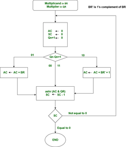
register R2 to register R1.Booth's Multiplication Algorithm Flow ChartWe name the register as A, B and Q, AC, BR and QR respectively. Qn designates the least significant bit of multiplier in the register QR. An extra flip-flop Qn+1is appended to QR to facilitate a double inspection of the multiplier.The flowchart for the booth algorithm is shown below.
Flow chart of Booth’s Algorithm.
AC and the appended bit Qn+1 are initially cleared to 0 and the sequence SC is set to a number n equal to the number of bits in the multiplier. The two bits of the multiplier in Qn and Qn+1are inspected. If the two bits are equal to 10, it means that the first 1 in a string has been encountered. This requires subtraction of the multiplicand from the partial product in AC. If the 2 bits are equal to 01, it means that the first 0 in a string of 0’s has been encountered. This requires the addition of the multiplicand to the partial product in AC. When the two bits are equal, the partial product does not change. An overflow cannot occur because the addition and subtraction of the multiplicand follow each other. As a consequence, the 2 numbers that are added always have a opposite signs, a condition that excludes an overflow. The next step is to shift right the partial product and the multiplier (including Qn+1). This is an arithmetic shift right (ashr) operation which AC and QR ti the right and leaves the sign bit in AC unchanged. The sequence counter is decremented and the computational loop is repeated n times. Product of negative numbers is important, while multiplying negative numbers we need to find 2’s complement of the number to change its sign, because it’s easier to add instead of performing binary subtraction. product of two negative number is demonstrated below along with 2’s complement.
Introduction of ALU and Data Path
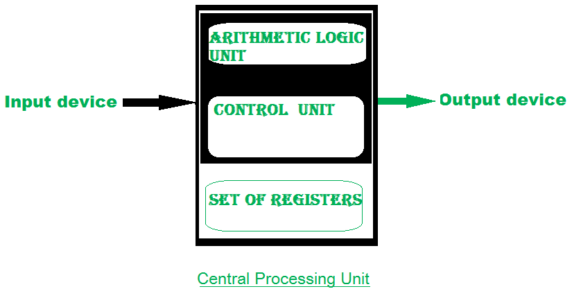
Representing and storing numbers were the basic operation of the computers of earlier times. The real go came when computation, manipulating numbers like adding, multiplying came into the picture. These operations are handled by the computer’s arithmetic logic unit (ALU). The ALU is the mathematical brain of a computer. The first ALU was INTEL 74181 implemented as a 7400 series is a TTL integrated circuit that was released in 1970.
The ALU is a digital circuit that provides arithmetic and logic operations. It is the fundamental building block of the central processing unit of a computer. A modern CPU has a very powerful ALU and it is complex in design. In addition to ALU modern CPU contains a control unit and a set of registers. Most of the operations are performed by one or more ALU’s, which load data from the input register. Registers are a small amount of storage available to the CPU. These registers can be accessed very fast. The control unit tells ALU what operation to perform on the available data. After calculation/manipulation, the ALU stores the output in an output register.
The CPU can be divided into two sections: the data section and the control section. The DATA section is also known as the data path.BUS: In early computers “BUS” were parallel electrical wires with multiple hardware connections. Therefore a bus is a communication system that transfers data between components inside a computer, or between computers. It includes hardware components like wires, optical fibers, etc and software, including communication protocols. The Registers, ALU, and the interconnecting BUS are collectively referred to as data paths.Types of the bus are:
- Address bus: The buses which are used to carry address.
- Data bus: The buses which are used to carry data.
- Control bus: If the bus is carrying control signals.
- Power bus: If it is carrying clock pulse, power signals it is known as a power bus, and so on.
The bus can be dedicated, i.e., it can be used for a single purpose or it can be multiplexed, i.e., it can be used for multiple purposes. When we would have different kinds of buses, different types of bus organizations will take place.
- Program Counter –
A program counter (PC) is a CPU register in the computer processor which has the address of the next instruction to be executed from memory. As each instruction gets fetched, the program counter increases its stored value by 1. It is a digital counter needed for faster execution of tasks as well as for tracking the current execution point.
- Instruction Register –
In computing, an instruction register (IR) is the part of a CPU’s control unit that holds the instruction currently being executed or decoded. An instruction register is the part of a CPU’s control unit that holds the instruction currently being executed or decoded. The instruction register specifically holds the instruction and provides it to the instruction decoder circuit.
- Memory Address Register –
The Memory Address Register (MAR) is the CPU register that either stores the memory address from which data will be fetched from the CPU, or the address to which data will be sent and stored. It is a temporary storage component in the CPU(central processing unit) that temporarily stores the address (location) of the data sent by the memory unit until the instruction for the particular data is executed.
- Memory Data Register –
The memory data register (MDR) is the register in a computer’s processor, or central processing unit, CPU, that stores the data being transferred to and from the immediate access storage. Memory data register (MDR) is also known as memory buffer register (MBR).
- General Purpose Register –
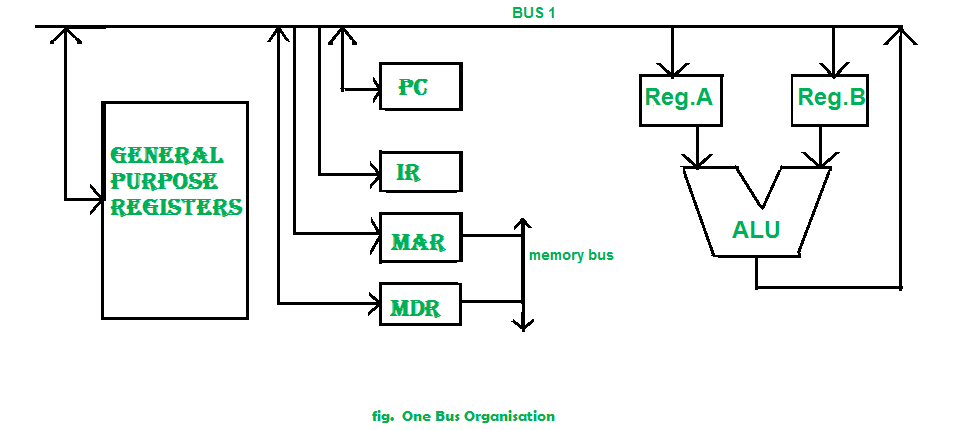
General-purpose registers are used to store temporary data within the microprocessor. It is a multipurpose register. They can be used either by a programmer or by a user.One Bus organization –
In one bus organization, a single bus is used for multiple purposes. A set of general-purpose registers, program counters, instruction registers, memory address registers (MAR), memory data registers (MDR) are connected with the single bus. Memory read/write can be done with MAR and MDR. The program counterpoints to the memory location from where the next instruction is to be fetched. Instruction register is that very register will hold the copy of the current instruction. In the case of one bus organization, at a time only one operand can be read from the bus.
As a result, if the requirement is to read two operands for the operation then the read operation needs to be carried twice. So that’s why it is making the process a little longer. One of the advantages of one bus organization is that it is one of the simplest and also this is very cheap to implement. At the same time a disadvantage lies that it has only one bus and this “one bus” is accessed by all general-purpose registers, program counter, instruction register, MAR, MDR making each and every operation sequential. No one recommends this architecture nowadays.
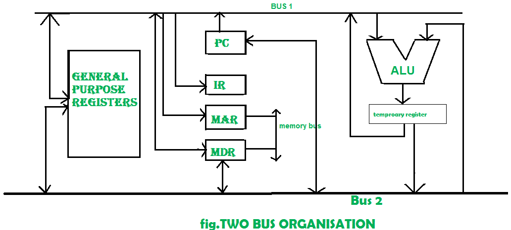
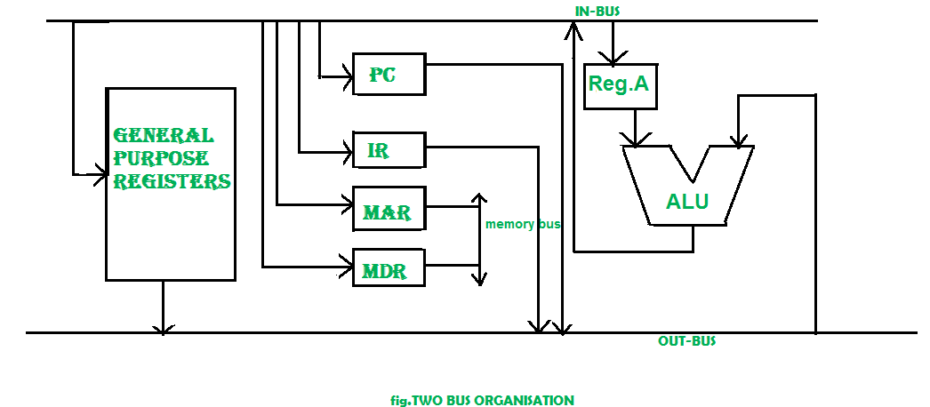
Two Bus organizations –
To overcome the disadvantage of one bus organization another architecture was developed known as two bus organization. In two bus organizations, there are two buses. The general-purpose register can read/write from both the buses. In this case, two operands can be fetched at the same time because of the two buses. One bus fetch operand for ALU and another bus fetch for register. The situation arises when both buses are busy fetching operands, the output can be stored in a temporary register and when the buses are free, the particular output can be dumped on the buses.There are two versions of two bus organizations, i.e., in-bus and out-bus. From in-bus, the general-purpose register can read data and to the out bus, the general-purpose registers can write data. Here buses get dedicated.
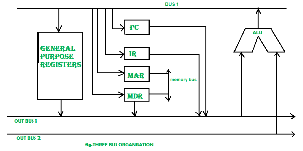
Three Bus organization –
In three bus organizations we have three buses, OUT bus1, OUT bus2, and an IN bus. From the out buses, we can get the operand which can come from the general-purpose register and evaluated in ALU and the output is dropped on In Bus so it can be sent to respective registers. This implementation is a bit complex but faster in nature because in parallel two operands can flow into ALU and out of ALU. It was developed to overcome the “busy waiting” problem of two bus organizations. In this structure after execution, the output can be dropped on the bus without waiting because of the presence of an extra bus. The structure is given below in the figure.
The main advantages of multiple bus organizations over the single bus are as given below.
- Increase in size of the registers.
- Reduction in the number of cycles for execution.
- Increases the speed of execution or we can say faster execution.
Tirthankar Pal
MBA from IIT Kharagpur with GATE, GMAT, IIT Kharagpur Written Test, and Interview
2 year PGDM (E-Business) from Welingkar, Mumbai
4 years of Bachelor of Science (Hons) in Computer Science from the National Institute of Electronics and Information Technology
Google and Hubspot Certification
Brain Bench Certification in C++, VC++, Data Structure and Project Management
10 years of Experience in Software Development out of that 6 years 8 months in Wipro
Selected in Six World Class UK Universities:-
King's College London, Durham University, University of Exeter, University of Sheffield, University of Newcastle, University of Leeds


No comments:
Post a Comment